
Mahdi Ahmadi
Contact address: mahdi.ahmadi.6th@gmail.com

Table of Contents
- Introduction
- Components
- How to Calculate the Resistor Value
- Set up Blynk IoT Cloud
- Source Code
- Project Demo
- References
Introduction
Welcome to this tutorial! In this guide, we’ll learn how to create an IoT-based Gas Leakage Detection System using the NodeMCU board and the MQ-2 gas sensor. This project integrates IoT technology, allowing you to monitor and control the system remotely from your mobile phone using the Blynk app.
The primary goal of this project is to design a low-cost, home security solution that can detect dangerous gas leaks and send notifications to your phone. It is particularly useful for preventing accidents caused by gas leakage, providing a convenient way to stay informed and alert even when you are not at home.
The system works by using the MQ-2 sensor to detect gas leakage. Once the sensor detects a gas leak, the system triggers an alert mechanism including a buzzer and LEDs, while simultaneously sending a push notification to your smartphone. Additionally, the gas levels are displayed on an LCD screen and the Blynk app interface, making it easy to monitor the status of the system in real-time.
This project is an excellent example of how IoT can be applied in everyday life to improve safety and security.
Components
To build the Gas Leakage Detection System, you will need the following components: | Component | Quantity | Description/Link | |—————————–|————–|——————————| | NodeMCU (ESP8266) | 1 | A Wi-Fi development board to connect the sensor and send data to the Blynk app. | | MQ-2 Gas Sensor | 1 | A sensor for detecting gases like LPG, smoke, and carbon monoxide. | | 16x2 LCD Display | 1 | To display gas levels and system status. | | I2C Module | 1 | For simplifying connections between the LCD and NodeMCU. | | Buzzer | 1 | Provides an audible alert when a gas leak is detected. | | Red LED | 1 | Indicates a gas leak (on when a leak is detected). | | Green LED | 1 | Indicates normal operation (on when no leak is detected). | | 180-ohm Resistor | 2 | Used for limiting current to LEDs. | | Breadboard | 1 | For building the circuit without soldering. | | Jumper Wires | Several | For connecting components on the breadboard. |
The system is designed to be affordable and easy to assemble, making it a great project for anyone interested in learning about IoT and home automation.
here is the picture of some important components:
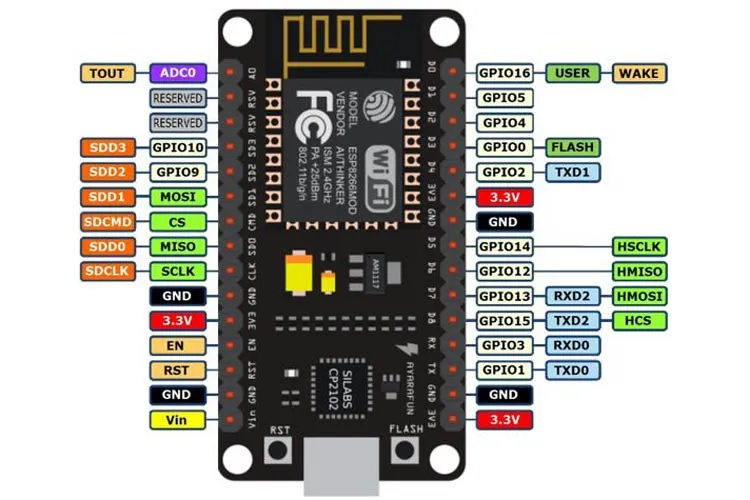
NodeMCU (ESP8266)
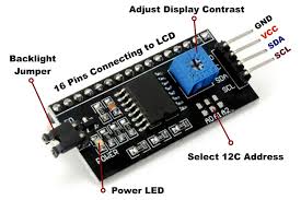
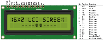
16x2 LCD Display and I2C Module
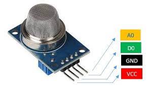
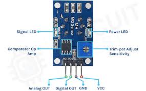
MQ-2 Gas Sensor
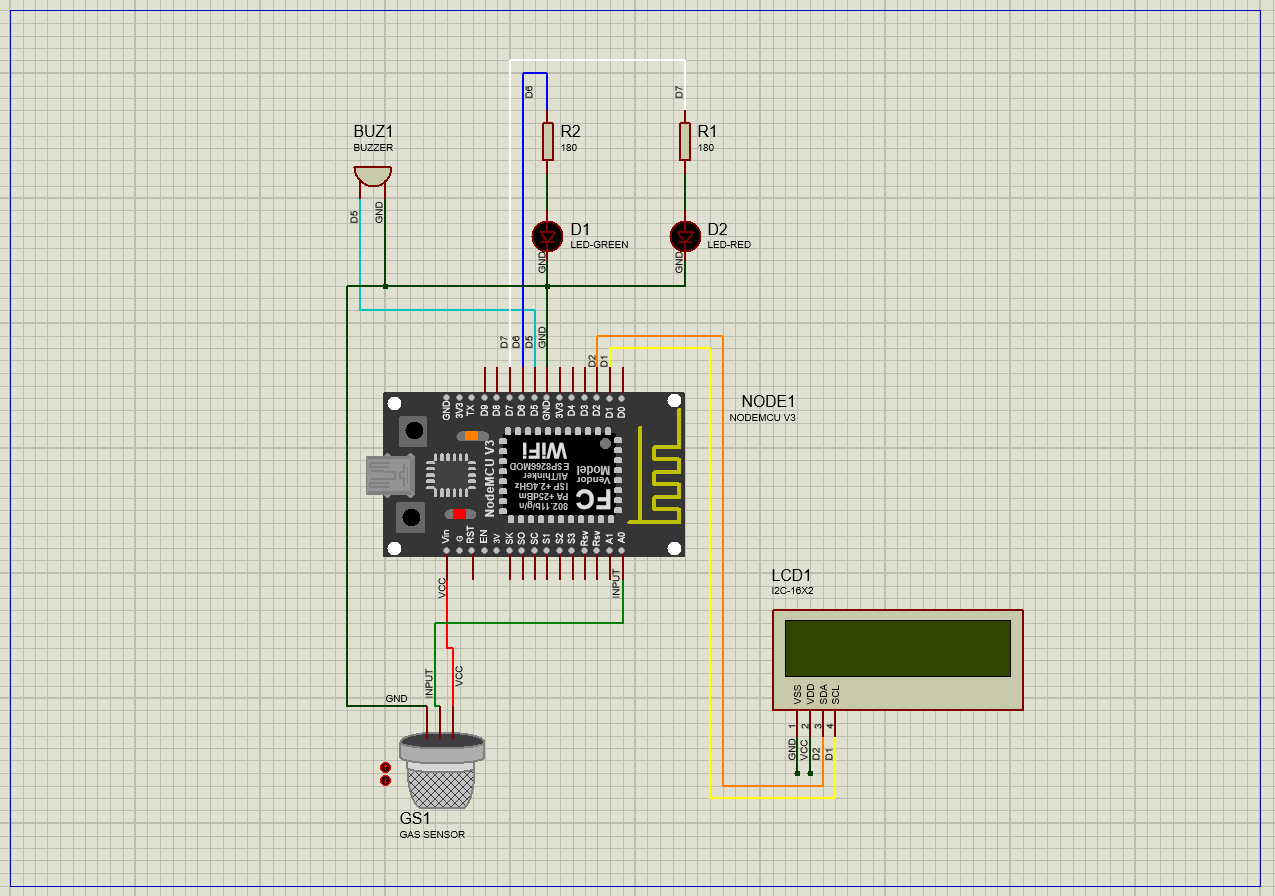
Circuit Diagram
Always use a resistor in series with an LED to limit the current and protect the component from damage.
How to Calculate the Resistor Value
Use Ohm’s Law to determine the appropriate resistor:
\[Min Resistor = \frac{V_{\text{supply}} - V_f}{Max Current}\]Where:
- V_supply : Power supply voltage (Volts)
- V_f : LED forward voltage (Volts)
- I : Desired LED current (Amps, e.g. 20 mA = 0.02 A)
LED Resistor Reference Table
| Power Supply | LED Vf | Max Current | Min Resistor (Ω) |
|---|---|---|---|
| 3V | 2.0V | 20 mA | 50 Ω |
| 4.5V | 2.0V | 20 mA | 125 Ω |
| 5V | 2.0V | 20 mA | 150 Ω |
| 9V | 2.0V | 20 mA | 350 Ω |
| 3V | 3.0V | 20 mA | LED OFF |
| 4.5V | 3.0V | 20 mA | 75 Ω |
| 5V | 3.0V | 20 mA | 100 Ω |
| 9V | 3.0V | 20 mA | 300 Ω |
Note: If the supply voltage is equal to or less than the LED’s forward voltage, the LED will not light up.
Set up Blynk IoT Cloud
First, go to the Blynk Website and log in.
Step 1: Log In
Click on Log In and enter your account credentials.
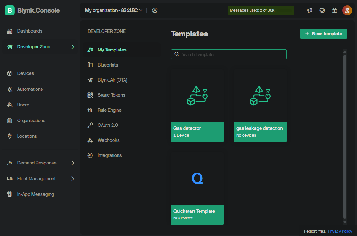
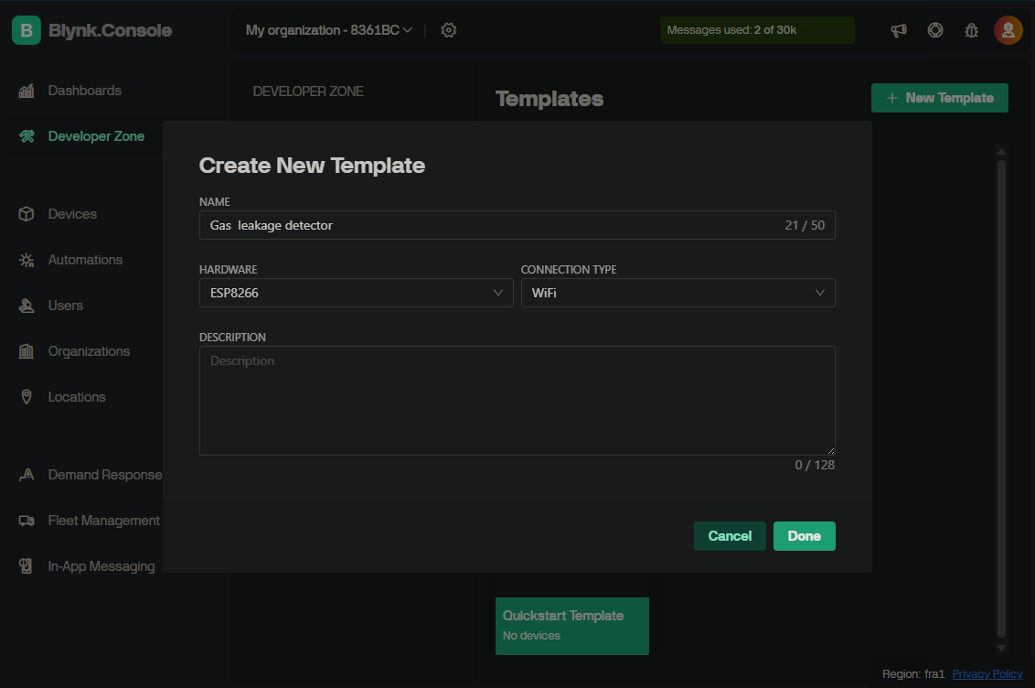
Step 2: Create a New Template
Now we are going to create a new template for this project.
- In the Dashboard, click on the Developer Zone tab.
- Then select My Templates.
- Click on the New Template button.
You can also use the Quickstart Template, but it provides fewer configuration options.
Step 3: Configure the Template
Now configure your template settings.
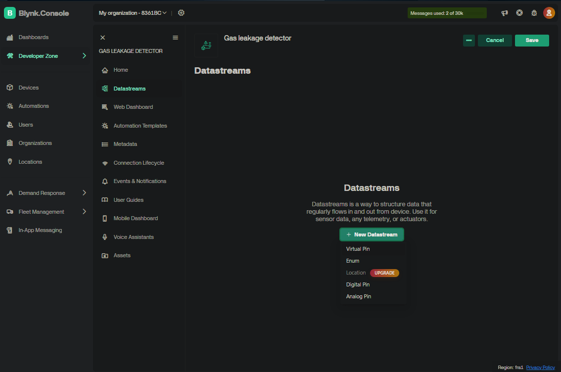
Step 4: Create Datastreams
Now we need to create two datastreams for our project:
- One for reading the gas sensor value.
- One for controlling the system (ON/OFF switch).
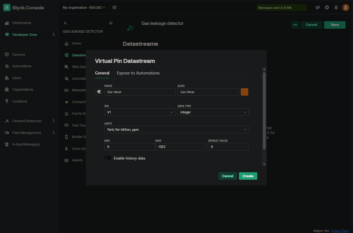
1. Create Gas Sensor Datastream
- In your template, go to the Datastreams tab.
- Click on New Datastream and select Virtual Pin.
- Set the following options:
- Name: Gas Value
- Virtual Pin: V1
- Data Type: Integer
- Min Value: 0
- Max Value: 1023
- Unit: AQ (or PPM)
- Then click Create.
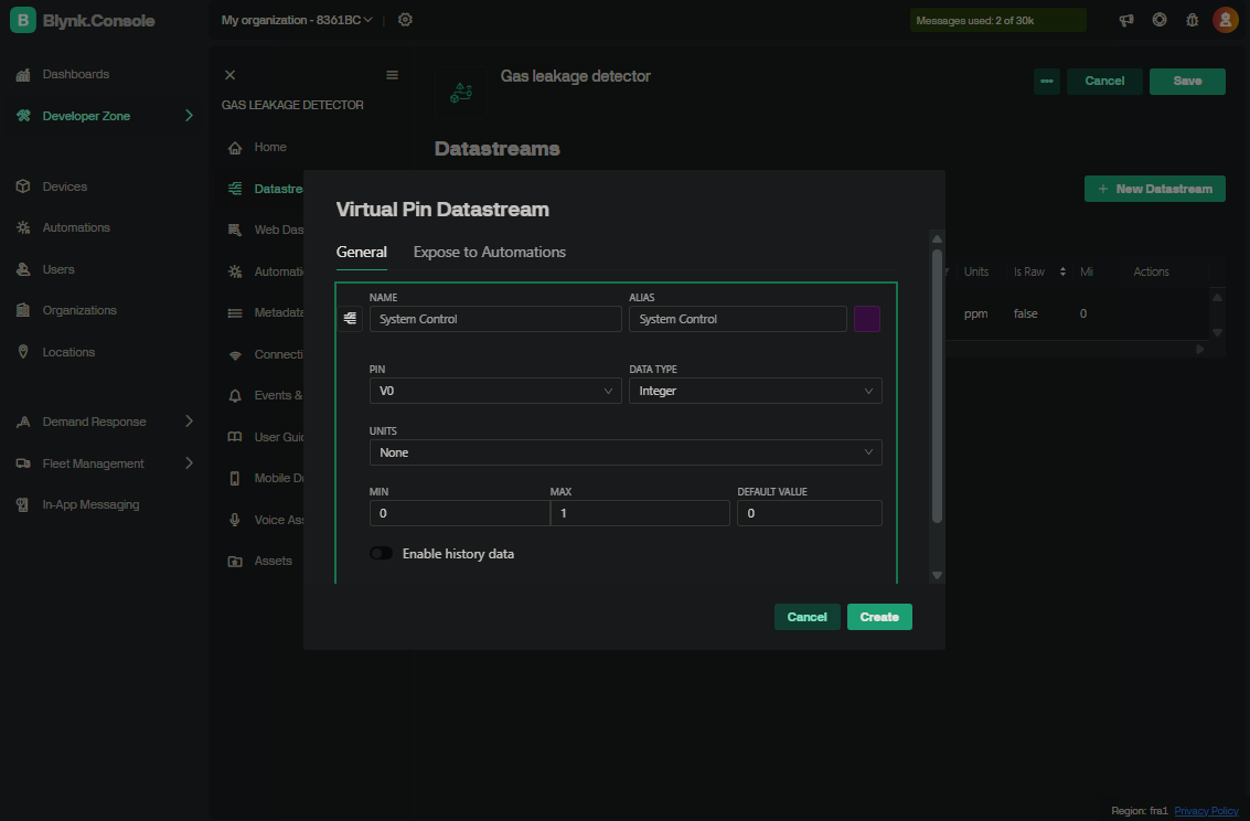
2. Create Switch Control Datastream
- Again, click on New Datastream and select Virtual Pin.
- Set the following options:
- Name: System Control
- Virtual Pin: V0
- Data Type: Integer
- Min Value: 0
- Max Value: 1
- Then click Create.
Step 5: Set Up the Dashboard
At this stage, you must design a dashboard to monitor and control your system. You can either use the Web Dashboard or the Mobile Dashboard, depending on your preference. In this guide, we are showing how to use the Web Dashboard, but the same widgets and data bindings are available on the mobile app as well.
1. Open Web Dashboard
- In your template, go to the Web Dashboard tab.
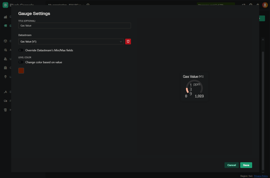
2. Add Gas Sensor Display
- Select the Gauge widget.
- Drag and place it where you want.
- Click on the widget to edit its settings:
- Datastream: Select Gas Value (V1).
- Label: Gas Level

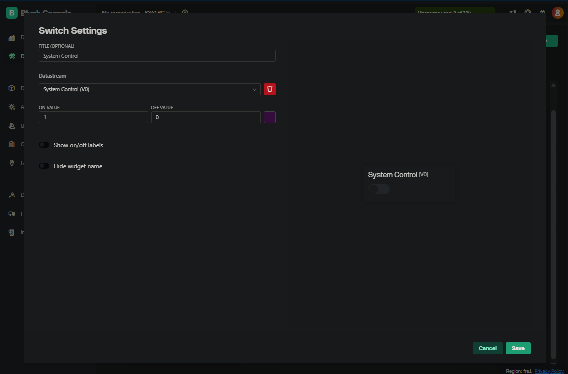
3. Add System Control Switch
- Select the Switch widget.
- Drag and place it.
- Click on the widget to edit its settings:
- Datastream: Select System Control (V0).
- Label: System ON/OFF
4. Save Changes
After adding and configuring the widgets, click Save to apply the changes.
Step 6: Add Device
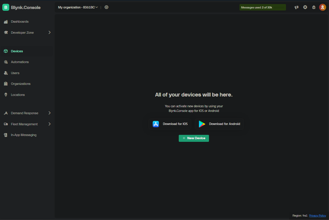
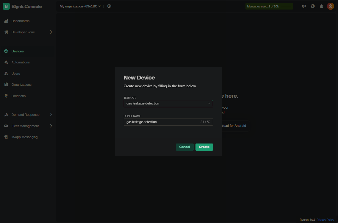
After setting up the template and Web Dashboard, it’s time to create a device based on your template.
1. Go to the Devices Page
- In the Dashboard, click on the Devices tab.
- Then click New Device.
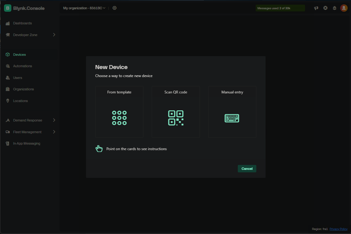
2. Create Device from Template
- Select From Template.
- Choose your created template.
- Give your device a name.
- Click Create.
3. Get Authentication Token (Auth Token)
- After the device is created, open the Device Settings (click on Developer Tools).
- You can either copy the Auth Token directly, or copy the complete Firmware Configuration from the Firmware Info section, as shown below.
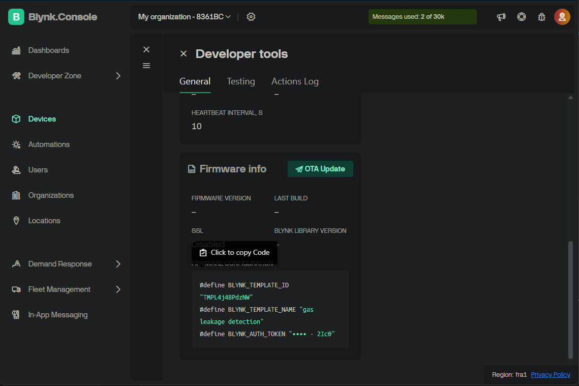
You will need this token later when programming your NodeMCU (ESP8266) to connect to the Blynk Cloud.
Step 7: Enable Notifications (Optional but Recommended)
To receive notifications (e.g. alerts when gas levels are high), you need to define an event in Blynk and enable push notifications.
Steps:
- Go to the Event & Notification section in the Blynk Console (from the left sidebar).
- Click New Event to create a custom event.
- Fill in the required details such as:
- Event Name (e.g.
Gas_Alert) - Severity Level (e.g. Warning or Critical)
- Notification Settings
- Event Name (e.g.
- Make sure to enable push notifications so that you receive alerts via the mobile app.
⚠️ Important:
Push notifications only work if you are logged into the Blynk mobile app with notifications enabled for the app on your phone.
Once the event is configured and triggered from your device’s code (e.g. via Blynk.logEvent("Gas_Alert")), you’ll get a notification on your phone instantly.
Source Code:
Note
You need to change the following credentials before uploading the code to your ESP8266:#define BLYNK_TEMPLATE_ID "TMPL4j48PdzNW" #define BLYNK_TEMPLATE_NAME "gas leakage detection" #define BLYNK_AUTH_TOKEN "vM_Sx9J_PK_6RYtQZCvijW6_OlN72Ic0" char ssid[] = "xxxxxxxxxx"; char pass[] = "xxxxxxxxxx";
The above details should be updated according to your specific WiFi network and Blynk credentials.
Then We Uploading the Code In ESP8266
// Blynk template credentials
#define BLYNK_TEMPLATE_ID "TMPL4ezsC8keZ"
#define BLYNK_TEMPLATE_NAME "gas leakage detection"
#define BLYNK_AUTH_TOKEN "UnSt9REz59sPpVGMfypVL2iebBSuWbZt"

#include <ESP8266WiFi.h>
#include <BlynkSimpleEsp8266.h>
#include <Wire.h>
#include <LiquidCrystal_I2C.h>

// Pin and threshold definitions
#define MQ_PIN A0              // Analog pin connected to MQ gas sensor
#define BUZZER D5              // Buzzer pin
#define LED_NORMAL D6          // Green LED - Normal status
#define LED_ALERT D7           // Red LED - Gas alert
#define GAS_THRESHOLD 900      // Threshold for gas detection

// Wi-Fi credentials
char ssid[] = "your wifi";
char pass[] = "password of wifi";

// LCD and Blynk timer
LiquidCrystal_I2C lcd(0x27, 16, 2);
BlynkTimer timer;

// Flag to control system ON/OFF via Blynk switch
bool systemActive = true;

// Blynk virtual pin V0 - Toggle system ON/OFF
BLYNK_WRITE(V0) {
  int value = param.asInt();
  systemActive = (value == 1);

  if (systemActive) {
    Serial.println("System activated");
    lcd.setCursor(0, 1);
    lcd.print("System ON       ");
  } else {
    Serial.println("System deactivated");
    lcd.setCursor(0, 1);
    lcd.print("System OFF      ");

    // Turn off all outputs
    digitalWrite(LED_ALERT, LOW);
    digitalWrite(LED_NORMAL, LOW);
    digitalWrite(BUZZER, LOW);
  }
}

// Send sensor data to Blynk
void sendToBlynk() {
  if (!systemActive) {
    Blynk.virtualWrite(V1, "System Off");
    return;
  }

  int gasValue = analogRead(MQ_PIN);
  Blynk.virtualWrite(V1, gasValue);

  if (gasValue > GAS_THRESHOLD) {
    Blynk.virtualWrite(V1, "Gas Alert!");
    Blynk.logEvent("gas_alert", "Gas level is HIGH!");
  } else {
    Blynk.virtualWrite(V1, "Normal");
  }
}

void setup() {
  Serial.begin(115200);

  pinMode(MQ_PIN, INPUT);
  pinMode(LED_NORMAL, OUTPUT);
  pinMode(LED_ALERT, OUTPUT);
  pinMode(BUZZER, OUTPUT);

  // Initial hardware states
  digitalWrite(LED_NORMAL, HIGH);
  digitalWrite(LED_ALERT, LOW);
  digitalWrite(BUZZER, LOW);

  // Initialize LCD
  lcd.init();
  lcd.backlight();
  lcd.setCursor(0, 0);
  lcd.print("Gas Detector");
  delay(1000);
  lcd.clear();

  // Connect to Blynk
  Blynk.begin(BLYNK_AUTH_TOKEN, ssid, pass);
  timer.setInterval(1000L, sendToBlynk); // Run every 1 second
}

void loop() {
  Blynk.run();
  timer.run();

  if (!systemActive) {
    return;  // System is off; skip all processing
  }

  int gasValue = analogRead(MQ_PIN);
  Serial.print("Gas value: ");
  Serial.println(gasValue);

  // Display gas value on LCD
  lcd.setCursor(0, 0);
  lcd.print("Gas: ");
  lcd.print(gasValue);
  lcd.print("    "); // Clear extra characters

  // Gas leak detection
  if (gasValue > GAS_THRESHOLD) {
    digitalWrite(LED_NORMAL, LOW);
    digitalWrite(LED_ALERT, HIGH);
    digitalWrite(BUZZER, HIGH);

    lcd.setCursor(0, 1);
    lcd.print("!!! GAS ALERT !!!");

  } else {
    digitalWrite(LED_NORMAL, HIGH);
    digitalWrite(LED_ALERT, LOW);
    digitalWrite(BUZZER, LOW);

    lcd.setCursor(0, 1);
    lcd.print("Status: Normal   ");
  }

  delay(1000); // Basic delay for stability
}
Project Demo
In this project, I tested the gas leakage detection system by turning on the gas. After a few seconds, the MQ-2 sensor detected the gas. The Blynk Web Dashboard showed the gas status with a red LED indicator, while the LCD displayed an alert message and the buzzer beeped.
When the gas level is below 900, the system returns to a normal condition: the green LED turns on, and the buzzer stops beeping.
References
MQ2 Gas Leakage Detection with Blynk Notification – JustDoElectronics
MQ2 Gas Sensor & Rain Detection with Blynk – IoT Circuit Hub
MQ2 Gas Leakage Smoke Detection System – Viral Science
LED Resistor Values for Current Limiting – GS Network
Some parts of this project were inspired by the tutorials listed above.