Tilt_sensor
Table of Contents
Introduction
Methodology
What It Does
How It Works
Two-Axis Tilt Sensors
Values
Types of tilt Sensors
Applications
Varients
Problems
Tilt sensor circuit
Results and Discussion
Conclusion
References
Author Information
Name: Zeinab Vakilzade
Affiliation: Department of Computer Engineering,Ferdowsi University of Mashhad
Contact: zeinabvakilzade@gmail.com
1.Introduction
Tilt sensors (inclinometers or tilt sensors) are designed for high-precision measurement of horizontal and vertical angular slopes. Tilt sensors are among the most common sensors used in various applications. They are used to measure slope position by referencing gravity and to identify the inclination or orientation of an object. If we intend to measure the tilt angle, which means inclination or deviation from vertical, we need to use receivers that contain tilt sensors. In surveying receivers, using this sensor provides significant advantages, as it allows us to obtain the tilt angle effect in situations where it’s not possible to keep the receiver perfectly vertical. The tilt effect is eliminated using this system, making it easy to obtain the precise position of a point. Since obtaining accurate information in surveying is extremely important, it’s essential to use sensors that provide the best results.
2. Methodology
2.1 What It Does
Three principal types of tilt sensor exist:
1.Single axis, single output. The sensor responds to being tilted around one horizontal axis, relative to the downward force of gravity.
2.Dual axis, dual output. The sensor contains two sensing elements at 90 degrees to each other. Each has an output determined by its angle of tilt from vertical around one axis.
3.Dual axis, single output. A single sensor responds to an angle of tilt from vertical around any horizontal axis.
A tilt switch is usually of the third type.
2.2 How It Works
Because a tilt switch is a simpler device than a tilt sensor, it will be described first. The most common type of tilt switch consists of a cylindrical metal or plastic enclosure, often measuring about 5mm by 15mm, containing two spherical steel balls that may be nickel plated or gold-plated. When the switch is tilted, the balls eventually run downhill, and the lower ball completes an electrical connection between two contacts or between a single contact and the metal enclosure of the switch. The second ball is included to add weight and suppress vibration in the first.
Application of a tilt switch:
1.Security and Alarm System
2.Automotive and Transportation
3.Home Appliances
Unlike a tilt switch, a tilt sensor is not built around an electromechanical switch. The principle of a rolling ball has been miniaturized and encapsulated in a small enclosure (10mm square or smaller), in which the ball rolls to interrupt a beam from an internal LED shining on a phototransistor.
Advantages over a Mechanical Tilt Switch:
- Higher Sensitivity and Precision: It operates using light, making it less susceptible to minor vibrations and only triggering upon an actual, definitive tilt.
- Longer Lifespan: There are no metal contacts that can wear out from physical slapping or oxidation.
- Higher Reliability: It is immune to issues like contact bouncing and corrosion, providing a more stable and consistent digital signal.
This type of sensor is used in more precise devices such as some smartphones, robots, or sensitive industrial equipment.
2.3 Two-Axis Tilt Sensors
The Rohm RPI-1035 is a surface-mount tilt sensor about 4mm square, with two phototransis- tor outputs that indicate which axis the sensor is tilting around. The outputs can be interpreted as a 2-bit binary number, with its four possible states indicating the rotation of the switch around two axes at 90 degrees to each other. Switches of this type were developed to indicate the orientation of consumer electronic devices such as digital cameras.
2.4 Values
More commonly, a tilt switch about 15mm long can be expected to switch about 0.3A at 24VAC or 24VDC. The operating angle is the angle through which the switch must be turned to activate it, relative to its normal rest position. The return angle is the angle to which the switch must be returned to deactivate it. Hysteresis results from the return angle being smaller than the angle that activates the sensor.
2.5 Types of tilt Sensors
1.Resistive Tilt Sensor These sensors contain a suspended mass that displaces when tilted, causing a change in resistance. The simplest type is used in toys or basic alarm systems.
2.Capacitive Tilt Sensor This type of sensor uses changes in capacitance to detect angular variations. When an object moves within the capacitor’s electric field, the distance between the plates or the shape of the field changes, altering the capacitance. This change is converted into an electrical signal to determine the tilt angle.
Features:
· High accuracy
· Small size
· No mechanical contact required
3.MEMS Tilt Sensor MEMS (Micro-Electro-Mechanical Systems) refers to technologies where mechanical and electronic systems are manufactured on a micro-scale. MEMS tilt sensors use a microscopic suspended mass between capacitors. The displacement of this mass due to tilt causes a change in capacitance.
-
Advantages:
· Very small size
· Cost-effective
· Low power consumption
-
Applications:
· Mobile phones and tablets
· Industrial robots
· Automotive safety systems
4.Electrolytic Tilt Sensor
These sensors contain a conductive fluid housed in a special chamber. When tilted, the fluid’s position changes, altering the resistance between electrodes. These changes indicate the tilt angle.
Advantages:
· High accuracy
· Suitable for harsh industrial conditions
And more…
2.6 Applications
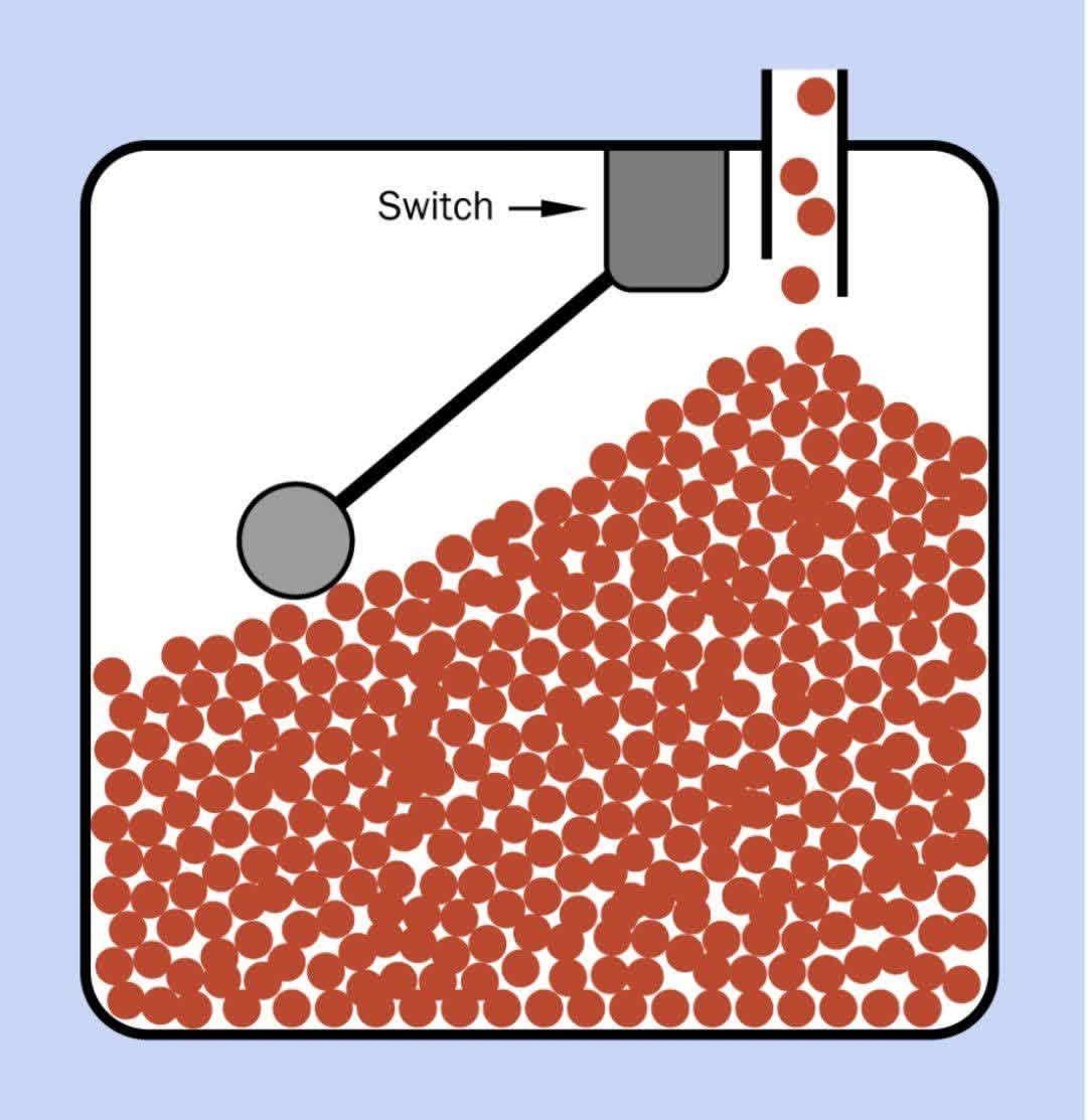
An old-style (nonelectronic) thermostat may contain a tilt switch attached to the end of a bimetallic strip coiled into a spiral. When the strip bends in response to a drop in temperature, the switch closes its contacts, activating arelay that starts a heating unit. If the temperature rises, an additional set of contacts in the same relay may activate an air-conditioning unit. In old thermostats, the tilt switch may contain mercury in a glass tube, which should be handled with caution. A tilt switch may detect the opening of a door or window in a simple alarm system. Tilt switches have been used in automobiles to switch on the interior light in the trunk when its lid is opened. A normally tilt switch is often used to stop the inflow of granular material to a bin when it is almost full. This is colloquially known as a bin switch. In industrial applications of this kind, the switch is activated by a long lever that has a ball mounted at the end.
A normally tilt switch may operate a valve or start a pump when the liquid in a tank drops below a certain point. If the switch uses a float to sense the level of the liquid, it is often known as a float switch.
2.7 Varients
Mercury Switches:
Early tilt switches contained a blob of mercury in a glass bulb. When the bulb was tilted, the mercury rolled to the end and made an electric connection between two metal contacts that penetrated the bulb. This type of sensor became less common after many countries classified mercury as an environmental hazard and established regulations restricting its use.
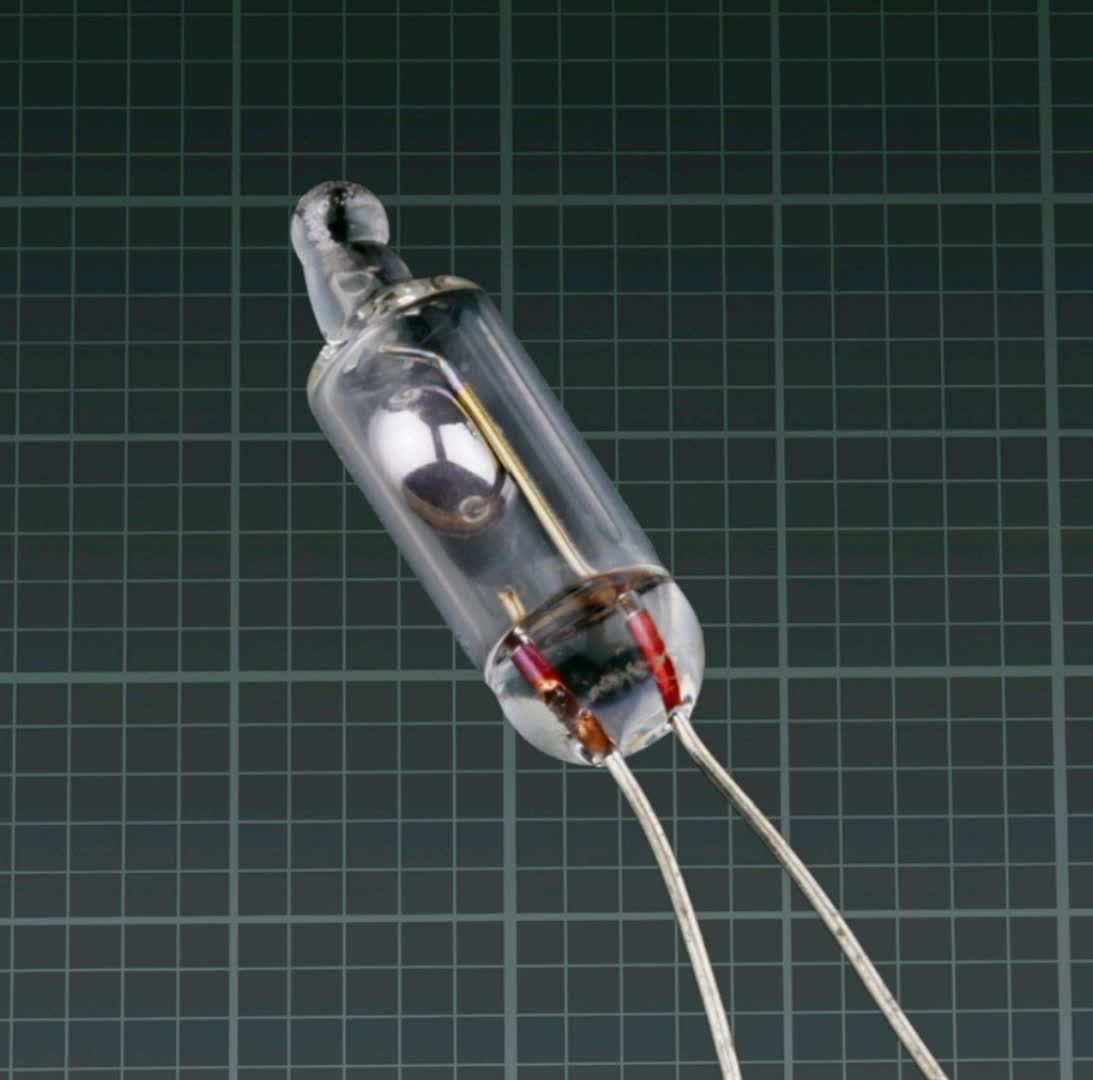
Mercury is an excellent electrical conductor. It remains in a liquid state between about -38 degrees Celsius and +356 degrees Celsius, and has very high surface tension, encouraging it to form a single blob instead of breaking up into small droplets. Because free space in the bulb is filled with an inert gas to prevent oxidation of the electrodes, a mercury switch can have a very long operating life.
Pendulum Switch:
It consists of a pendulum about 5cm long, suspended insidea steel ring about 1cm in internal diameter. If the machine was rocked sufficiently to bring the pendulum in contact with the ring, the game was cancelled and the word “Tilt” appeared on the display.
Magnetization:
Some tilt switches use a steel ball that is weakly magnetized, so that it will seat itself more firmly when it rolls into a circular depression or ring. This type of switch must be tilted back through a larger angle to dislodge the ball. Therefore it will exhibit greater hysteresis.
2.8 Problems
Contact Erosion:
If a ball-type tilt switch is subjected to current that exceeds its specification, arcing may erode its contacts, and they will become less reliable, especially if the contacts are plated with a thin metallic film that is eroded.
Random Signals:
During the brief time when a ball-type tilt switch is turning from one position to the other,vibration of the ball(s) inside it is likely to create erratic, random signals. If the output from the switch is being evaluated by a microcontroller,a debouncing routine may be insucient to prevent the random signals from being sensed, and some programming will be necessary to ignore the signals during this transitional phase. If the switch is connected directly to a relay, the intermittent signals may occur sufficiently rapidly that the relay will ignore them.
Environmental Hazard:
A device that incorporates a mercury switch may have to be re-engineered in the future if the availability of mercury switches becomes unreliable as a result of tighter environmental regulations. For the same reason, the end user may have difficulty replacing a mercury switch if it fails. Therefore, a ball-type tilt switch should be used instead of a mercury switch in any newly designed device.
Requirement for Gravity:
Because a tilt switch depends on gravity to roll a ball or move a blob of mercury, it will not work in low-gravity or zero gravity conditions for example, in a rocket during the unpowered phase of ascent and descent, or in an aircraft that performs aerobatic maneuvers. Performance of a tilt switch in a vehicle that accelerates or decelerates suddenly may also be unreliable.
Requirement for Stability:
A tilt switch will tend to give erroneous results in a location where there is significant vibration or where the object containing the switch may be turned or repositioned unpredictably by the user.
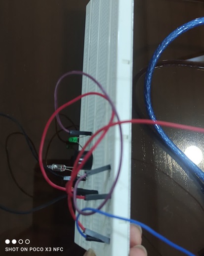
3. Tilt sensor circuit
To assemble the tilt sensor circuit,we need the following components:
- Arduino
- USB cable
- Several pieces of wire
- Breadboard
- Resistors
- Tilt sensor
- Buzzer
- LED
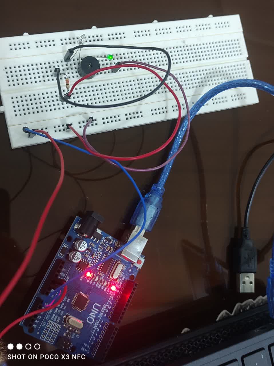
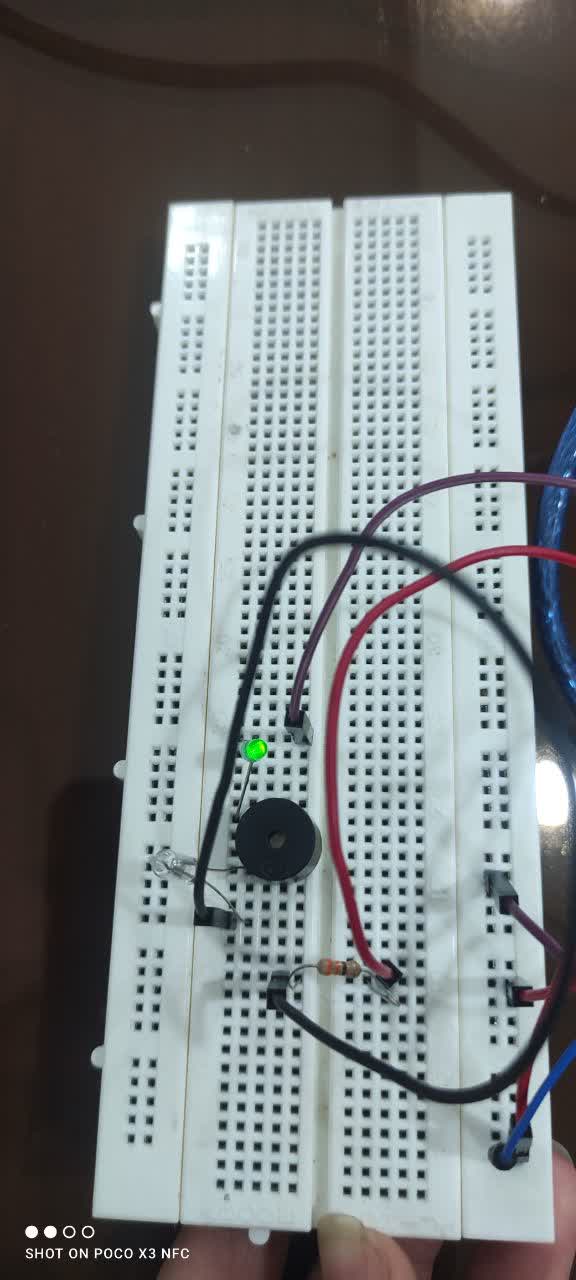
Construction method:
First,connect the Arduino to the system with a USB cable to act as the power source.then,connect one wire from the Arduino’s GND to the breadboard’s negative rail and another wire from the 5v pin to the breadboard’s positive rail.next,connect a wire from the breadboard’s positive rail to a resistor,then to a tilt sensor.connect the tilt sensor to a buzzer,then connect the buzzer to an LED. finally,connect the LED to the breadboard’s negative rail and record the results.
Notes:
When the breadboard is flat and stable,the mercury inside the tilt sensor connects the contacts,completing the circuit.
As a result,the buzzer (an electronic component) sounds and the LED lights up.However, if you tilt the breadboard slightly,the mercury moves away,breaking the connection.This causes the buzzer to stop sounding and the LED to turn off.
Conclusion:
In fact,in this circuit,the tilt sensor acts as a switch, connecting when the circuit is straight and disconnecting when the circuit is tilted.
4. Results and Discussion
1.Performance Comparison: Mechanical vs. Optical Sensors The results clearly show that theoptical sensor (based on LED and phototransistor) offers significant advantages over the mechanical sensor (based on a ball and contact). The optical sensor features higher sensitivity and precision, a longer lifespan (due to the absence of moving parts), and superior reliability, as it is immune to issues such as “contact bouncing” or “corrosion.” These characteristics make the optical sensor ideal for use in advanced devices such as robots and smartphones.
2.The Concept of Hysteresis and Its Importance The concepts of”operating angle” and “return angle” are crucial for understanding sensor accuracy. The presence of hysteresis—where the return angle is smaller than the operating angle—is a key finding. Although this characteristic could be considered a measurement error, in practice, it serves as an important advantage; it prevents the sensor from switching states repeatedly due to minor vibrations, thereby ensuring a stable output.
3.Application and Superiority of Dual-Axis Sensors The examination of dual-axis sensors,such as the Rohm RPI-1035, demonstrates that by providing two discrete outputs, these sensors enable direction detection across a full 360-degree horizontal plane. This capability makes them highly suitable for complex applications, such as determining the orientation of digital cameras.
5. Conclusion
Based on the analyses conducted in this project, it can be concluded that the selection of a tilt sensor is entirely dependent on the application requirements. For simple, low-precision applications such as alarm systems, mechanical sensors are a cost-effective and sufficient solution. However, for sensitive and precise applications in advanced electronics, the use of optical or dual-axis sensors is a necessity and a technologically superior option. These sensors, by utilizing a non-contact measurement principle, offer a longer lifespan and higher reliability, making them entirely suitable for use in robotics, precision instruments, and modern electronics.
6. References
https://blog.sanattech.com
https://hpi.co.com
https://en.wikipedia.org
ElectronicComponentsEncyclopedia.pdf